VCP
VERICUT Composites Programming
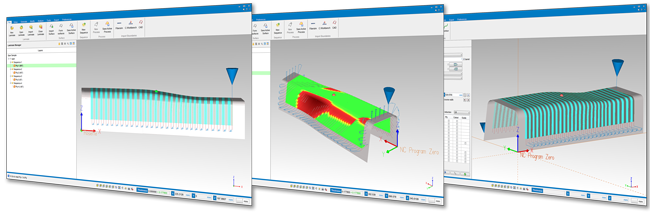
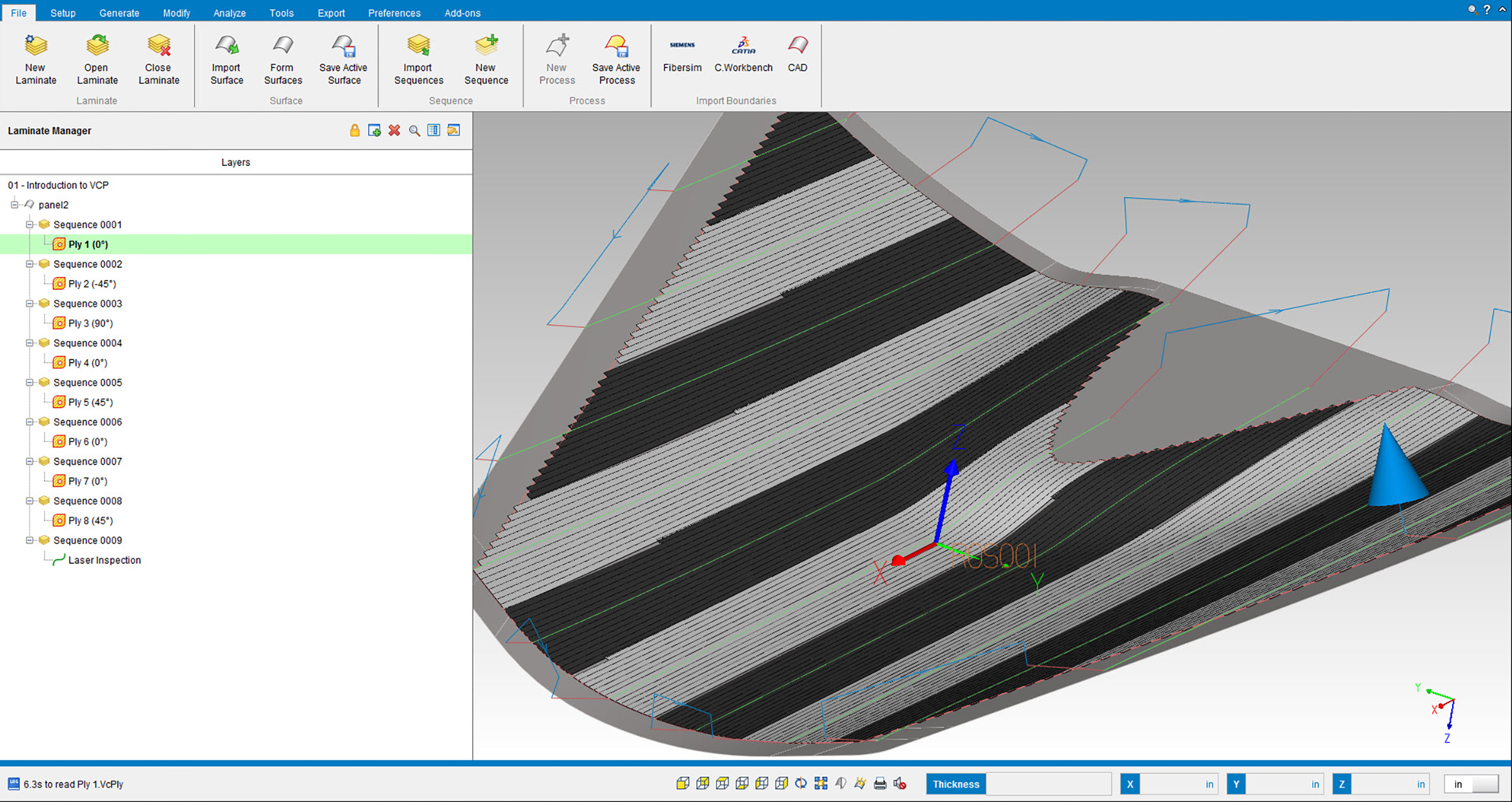
VERICUT Composites Programming (VCP) reads CAD surfaces and ply boundary information and adds material to fill the plies according to user-specified manufacturing standards and requirements. Layup paths are then linked together to form specific layup sequences and output as NC programs for the automated layup machine.
VERICUT Fiber Placement Programming Process:
Reads CATIA, STEP, Siemens NX, Pro E, Creo, SolidWorks, or ACIS surface models
Reads Fibersim, CATIA STEP, or SAT external ply geometry and information
• Boundary geometry
• Ply direction
• Axis or rosette system
• Start points
Creates Geometry within VCP
• Axis systems
• Points, lines, & curves
• Add thickness to form for subsequent sequences
Generates layup paths based on manufacturing engineering specifications
• Rosette projection at specified angles
• Parallel to guiding curve
• Following the natural path of the form’s surface
• Limited material steering
• And more…
Visualizes roller orientation
• Display roller and machine head to avoid collision
• Detect roller collision
• Visualize roller conformance to layup surface
Links paths to create form layup sequences
• Automatically or manually link paths based on shortest distance and form’s topology
• Insert machine-specific commands and actions
• Insert safe start and restart events
• Fully support spinning, stationary, and alternative rotisserie axes
Post-processes linked paths
• Output per machine requirements
• Configurable machine-specific events and feed rate optimizations
• Output safe start and restart sequences
Optimizes the quality process
• Export XML files for laser projectors
– Head paths, ply boundaries
– Safe restarts
– Tow Gaps & More
Calculates & balances material usage
• Keep track of material on each spool
• Alter head paths to re-distribute material
Checks material conformance
• *New* Heat map
• Visualize ply angle deviations, steering violations and roller compression
• Pin point most severe material violations
Analyzes gaps, overlaps, and staggers
• Highlight excessive overlaps, and gaps
• Calculate the sum of gaps and overlaps
• Control and stagger splice locations
• Visualize areas of course convergence
Excerpt from: Roadmap to Automated Composites
By: Charles B. Anderton, André Colvin
CGTech
Implementing automated composites requires a significant capital investment, alongside a steep learning curve. The expenditure in both cost and time inhibit many manufactures from instituting automation, despite the clear advantages. This paper will define important terminology, provide a business case for adopting automated composites, and point out considerations when deciding upon a machine. By shedding light onto these specific considerations, informed and successful steps can be taken to implement this constantly evolving technology.
Roadmap to Automated CompositesPDF Download
 Germany
 Italy
Italy USA
USA South Korea
 UK
UK India
India France
 China
China Japan
Japan